RGB LED With ATtiny85
I just found that the ATtiny85 actually has 3 PWM pins, not 2 (well you can push it to 4 I believe) so it seemed like the ideal test for my recently received RGB common cathode LED.
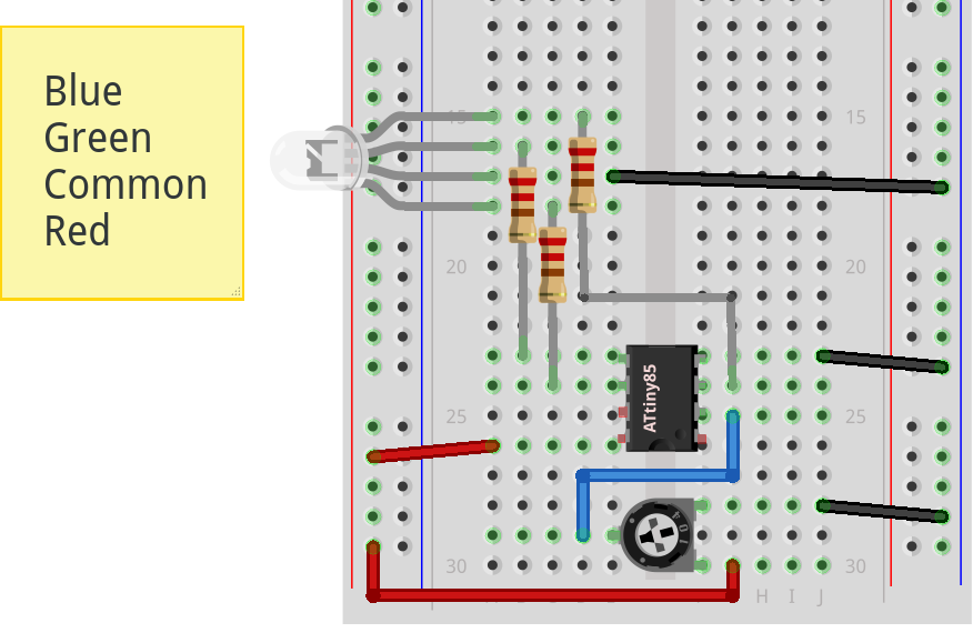
I setup the breadboard as shown below (doesn’t look great on Fritzing due to the weird way the LED is drawn sideways) note that the longer pin is the common cathode:
I used the arduino-tiny core with the recent round() macro fix for the ATtiny85-20PU at 8MHz, which I programmed using the ArduinoISP sketch. The code is as follows, inspired by Adafruit:
const int redPin = 1;   // 85 leg 6 (PB1), output to red channel
const int greenPin = 0; // 85 leg 5 (PB0), output to green channel
const int bluePin = 4;  // 85 leg 3 (PB4), output to blue channel
const int potPin = 3;   // 85 leg 2 (PB3)

void setup()
{
    // configure pins
    pinMode(redPin, OUTPUT);
    pinMode(greenPin, OUTPUT);
    pinMode(bluePin, OUTPUT);

    // demo red, green, blue first
    setColor(255, 0, 0);
    delay(1000);
    setColor(0, 255, 0);
    delay(1000);
    setColor(0, 0, 255);
    delay(1000);
}

void loop()
{
    // read pot value 0-1023, roughly 1024/256
    int reading  = analogRead(potPin) / 4;

    if (reading > 128)
    {
        // set red pin towards magenta based on pot
        setColor(reading, 0, 128);
    }
    else
    {
        // set blue pin towards cyan based on pot
        setColor(0, 255, reading);
    }
}

void setColor(int red, int green, int blue)
{
    analogWrite(redPin, red);
    analogWrite(greenPin, green);
    analogWrite(bluePin, blue);
}