Fitting an LDO to an ESP12F
I had a cunning plan to use the bottom half of my WIFI Witty board as a programmer for bare ESP-12F boards with those white breakouts, but then found that they rely on the regulator being on the ESP12, the whole of the Witty is 5v.
So I figured out that the solder pads on the underside of the breakouts are for a SOT-89 regulator, albeit with a stupid GND-VIN-VOUT pinout, so an LM1117T or suchlike wouldn’t do:
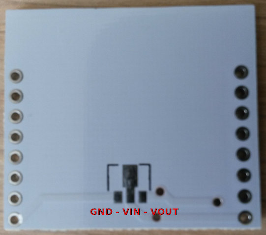
I found the Holtek HT7833 should do it as it has the correct pinout and 500mA output, so certainly enough for powering the ESP12 whilst programming, and probably enough for general use with wifi on.
So I soldered it in place and found that the ESP12 pins were still at about 5v. So after resoldering about three times (thought I’d bridged Vin/Vout) I looked at the traces on the white breakout and confirmed with my mulitmeter – they’ve bridged the Vin/Vout pins with a zero ohm resistor!
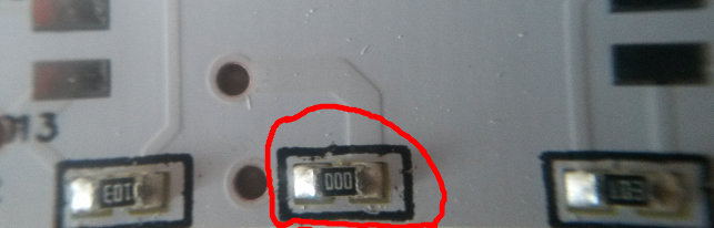
So I removed that with a disgusted slash of the soldering iron, and hey presto, 3.3v from CH_PD!
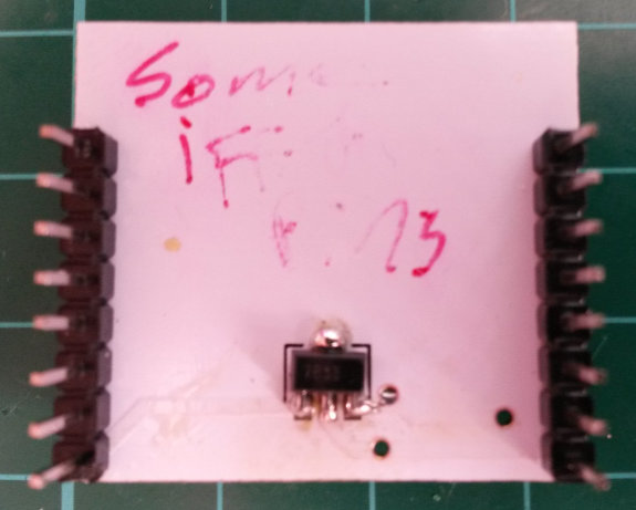
Here’s a photo of the soldered-in regulator, its pretty bad now as its been resoldered so many times, but it works, and that is my “some iffy pins” board.
So now I can program the bare ESP12 board (well, on its breakout) by sitting it on top of the Witty, just like you would with the board that comes with the Witty.
So in summary, if you want to fit a regulator you must:
- find a SOT-89 regulator with a GND-VIN-VOUT pinout which outputs over 300mA @ 3.3v, e.g. HT7833
- remove the zero ohm resistor on the topside of the white breakout