TP4056 Charger Boards
I thought I’d write up my findings when using the TP4056 Li-Ion charging boards as a lot of people seem to be interested in them lately for charging circuits containing ESP8266 wifi chips which are rated from about 3.3-3.6v. Ideally a Li-Ion, LiPo or LiFePo4 battery. Note that the TP4056 can’t be used to charge LiFePo4 batteries (or NiMH, Alkaline etc).
First up, a couple of links to Julian Ilett’s videos of the older unprotected USB-mini board and another video comparing the newer protected USB-micro board which some people refer to as MP1405.
The boards I received seem to be a slight modification on the newer boards, they have a green LED instead of a blue one and the chip layout is different, but still use the DW01 battery protection IC and 8205 mosfet to (dis)connect the charger. There doesn’t seem to be any reverse-polarity protection like a diode. I paid £1.36 for five.
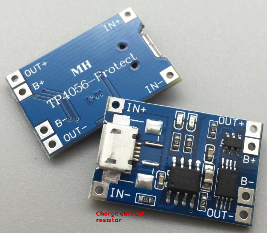
As my intended use was to allow my ESP8266 circuit to be enclosed in a box with no access to the battery, and be charged from any micro-USB source (computer, phone charger, powerbank, mains charger….) I swapped out the default 1k2 resistor (marked “122”, near IN-) which pulls around 900mA charge current, for a 2k2 one, which took the charge current down to about 540mA, only slightly above the average 500mA USB rating. It does slow down the charge rate, but would prevent poorly-built USB devices from pulling more current than they can handle. I used these 0603 metric (aka 0201 imperial) SMD resistors, which are just about hand-solderable – I actually managed to solder a through-hole resistor onto one board too!
There’s a couple of LED’s on the board:
Green on, red flashing = no battery
Red on, green off = charging
Green on, red off = charged
Both off = unplugged from USB
I was going to remove them to save quiescent current, but it turns out that when USB is disconnected (so you’re running off the battery) they are both turned off.
Also, you can still use your circuit when its plugged into USB, the “OUT+” outputs just under 4.2v irrespective of the battery’s charge (or even if the battery is disconnected). I’m not sure if it charges the battery whilst its powering a circuit, but believe so. Obviously the older mini-USB modules don’t have the output pads, they are purely for charging a battery, not powering a circuit.
One thing to note is that the modules seem to be optimised for being stored in a warehouse for a while, as they don’t actually turn on when you first connect a battery and measure about 150mV on all the pins. The answer is to plug them into USB, which then wakes the device. You can unplug them then if you like and they will output 3.7v from the battery on the OUT+ pin (or whatever the battery voltage is).
The board seems to get pretty hot whilst charging, which then cools as the battery voltage gets above about 4v and less current is flowing. The underside of my board got to 50c even with the 540mA charging current, according to a few websites this is the TP4056 chip itself, so I fitted a 6x6x3 heatsink that I had left over from a Raspberry Pi3 kit to the chip which seemed to drop the heat by about 5c, not sure if its worth it really.
Update: As I’ve bought a few 100mAh and 250mAh LiPo’s I made a multi-charge-current board which consists of a TP4056 with the two Rprog (R3) pads broken out onto perfboard, and then a 10k, 4k7, 2k2 and a 1k2 (1k+220r) resistor network with pin headers which can take a jumper to select the resistor to use. The resistors give me about 130mA, 260mA, 540mA and 1.1A, so always slightly over what you expect! I found also without a resistor at all it’ll pull 1.25A, but my biggest LiPo is 1000mAh so I didn’t push it, I’ll stick to a safe 1C. I 3D printed a case for both here.