ATtiny85 And Shift Registers
I decided I wanted to play with shift registers, and the classic circuit for that is running a bunch more LED’s from a chip than the chip has pins, so I decided on an 8 pin ATtiny85 running 16 LED’s as a Larson scanner (Knight Rider or Cylon effect).
I started out on breadboard which was a terrible mistake as I ended up needing two breadboards to provide enough space to run 16 LED’s via resistors all with a shared GND. Should have gone straight to perfboard (I think veroboard would have the same problem as breadboard due to solid tracks instead of pads).
The shiftOut() function takes a bit of getting used to, especially when using two 74HC595 shift registers so need to output 16 bits instead of an 8-bit byte (and when it takes an hour of playing with code to realise one of the chip’s output pins it busted!) and for some reason when moving from breadboard to perfboard I had to change the code to use MSBFIRST instead of LSBFIRST or it would run the LED sequence on each chip instead of across the two…..?!
Anyway, here’s the circuit diagram:
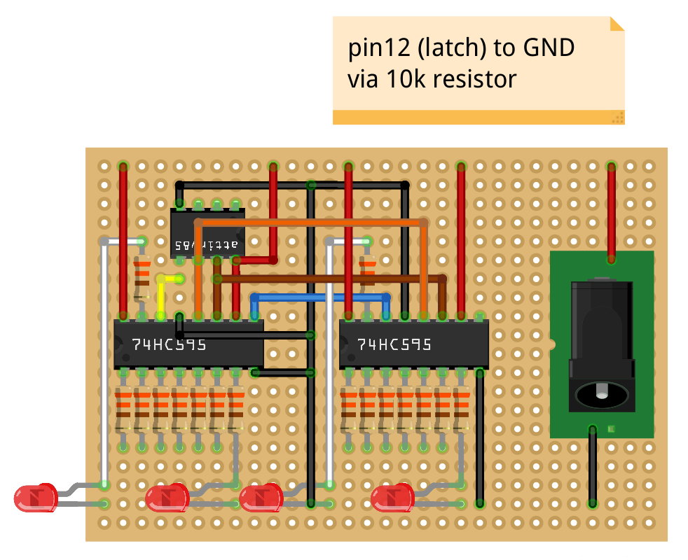
And here’s the code, where you can see I visualised the effect in binary split over the two registers, which then gets latched, shifted out twice, then unlatched. All using 3 pins from the ATtiny85!
const int latchPin = 1; // st_cp=12
const int clockPin = 2; // sh_cp=11
const int dataPin = 0; // ds=14

void write2Registers(byte patternA, byte patternB)
{
    // set latch low so output doesnt change whilst sending in data
    digitalWrite(latchPin, LOW);

    // shift out the bits
    shiftOut(dataPin, clockPin, MSBFIRST, patternA);
    shiftOut(dataPin, clockPin, MSBFIRST, patternB);

    // set latch high to send output
    digitalWrite(latchPin, HIGH);

    // pause
    delay(100);
}

void setup()
{
    // configure pins
    pinMode(latchPin, OUTPUT);
    pinMode(dataPin, OUTPUT);
    pinMode(clockPin, OUTPUT);
}

void loop()
{
    write2Registers(B00000000,B00000001);
    write2Registers(B00000000,B00000011);
    write2Registers(B00000000,B00000111);
    write2Registers(B00000000,B00001110);
    write2Registers(B00000000,B00011100);
    write2Registers(B00000000,B00111000);
    write2Registers(B00000000,B01110000);
    write2Registers(B00000000,B11100000);
    write2Registers(B00000001,B11000000);
    write2Registers(B00000011,B10000000);
    write2Registers(B00000111,B00000000);
    write2Registers(B00001110,B00000000);
    write2Registers(B00011100,B00000000);
    write2Registers(B00111000,B00000000);
    write2Registers(B01110000,B00000000);
    write2Registers(B11100000,B00000000);
    write2Registers(B11000000,B00000000);
    write2Registers(B10000000,B00000000);
    write2Registers(B11000000,B00000000);
    write2Registers(B11100000,B00000000);
    write2Registers(B01110000,B00000000);
    write2Registers(B00111000,B00000000);
    write2Registers(B00011100,B00000000);
    write2Registers(B00001110,B00000000);
    write2Registers(B00000111,B00000000);
    write2Registers(B00000011,B10000000);
    write2Registers(B00000001,B11000000);
    write2Registers(B00000000,B11100000);
    write2Registers(B00000000,B01110000);
    write2Registers(B00000000,B00111000);
    write2Registers(B00000000,B00011100);
    write2Registers(B00000000,B00001110);
    write2Registers(B00000000,B00000111);
    write2Registers(B00000000,B00000011);
}
And a Makefile for use with the arduino-tiny core:
ISP_PROG     	   = usbasp
BOARD_TAG          = attiny85at8
ALTERNATE_CORE     = tiny
AVRDUDE_OPTS       = -v

include /usr/share/arduino/Arduino.mk
Also to help debugging I wrote a simplified code that would light a single LED:
void turnOnLed(int led)
{
    digitalWrite(latchPin, LOW);

    if (led >= 8)
    {
        shiftOut(dataPin, clockPin, MSBFIRST, 1<<(led-8));
        shiftOut(dataPin, clockPin, MSBFIRST, 0);
    }
    else
    {
        shiftOut(dataPin, clockPin, MSBFIRST, 0);
        shiftOut(dataPin, clockPin, MSBFIRST, 1<<led);

    }

    digitalWrite(latchPin, HIGH);
}
Which you can then call from setup() for instance, so it only gets run once:
for(int i=0; i<16; i++)
{
    turnOnLed(i);
    delay(120);
}
I also found that sometimes when first powered on, the circuit it would flash on some random LED’s, this is (mostly) solved by putting 10k pull down resistors between the latch pins and GND so that the registers don’t get rubbish data sent to them when the microcontroller is booting. I tried controlling the OE or SRCLR pins from the ATtiny85 but it didn’t fix the problem which is weird as SRCLR is supposed to reset the registers to all zeroes and OE is supposed to enable output!
Someone mentioned they got it working by adding a 110k resistor between OE and VCC to keep it high during boot, then pulling it low in setup().
I also varied the brightness by using PWM on the OE pin by calling analogWrite(4, random(255)); but the effect was a bit naff. You could vary the speed using a trimpot and analogRead(3) I guess, but I’m all out of potentiometers.
The pinouts are:
74HC595:

Q1  = 1		16 = VCC
Q1  = 2		15 = Q0
Q3  = 3		14 = DS (data)
Q4  = 4		13 = OE (output enable - tie to gnd)
Q5  = 5		12 = ST_CP (latch)
Q6  = 6		11 = SH_CP (clock)
Q7  = 7		10 = SRCLR (clear - tie to vcc)
GND = 8		9  = SO

ATtiny85:

RST   = 1		8 = VCC
A3/D3 = 2		7 = D2/A1
A2/D4 = 3		6 = D1
GND   = 4		5 = D0