ESP8266 Arduino Port

I’ve been getting back into the ESP8266 now that there is an Arduino port for it. I’ve not used the full IDE, just installed the hardware core into my existing vanilla 1.6.3 IDE using this setup.

I then made a little DS18B20 and ESP-01 module, which runs off of 2xAA batteries which are boosted to 3.3v using the Pololu step-up regulator. It started off as a 3xAA battery setup with a diode dropping the voltage down from 3.9v to 3.1v:
Been Busy

I’ve been quite busy with the old electronics recently. I got an ATtiny2313 and ATmega1284P sample from Atmel and flashed the arduino-tiny and mighty-1284p cores respectively using the updated arduino-mk v1.5 which now supports Arduino IDE 1.6.3

Here is the 1284 running “Blink”:

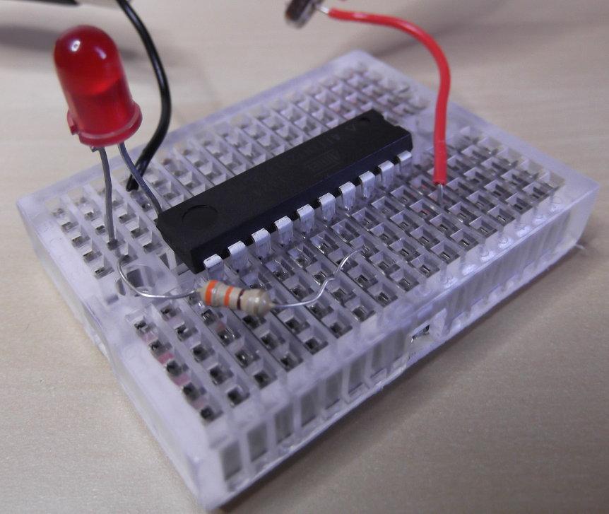
Here is the 2313 on a micro breadboard using only a resistor, LED and 5v/GND wires to run Blink:

img

The 2313 Makefile looks like:

ISP_PROG = usbasp
BOARD_TAG = attiny2313at1
ALTERNATE_CORE = tiny

include /usr/share/arduino/Arduino.mk

And we upload a sketch using “make ispload”.

Arduino and Wii Nunchuck Laser Turret

I finished my Arduino laser turret. Never did figure out why my bench supply seems to reset the circuit when connected to the veroboard but not the breadboard, but it works fine with 4x AA Eneloops, which at full charge give 5.26v

Bill of materials came to this lot plus a 330ohm resistor and a 2N2222 transistor:

I’ve tried this on a Nano3, Mega2560r3 and SF Pro Micro, but ended up sticking with the Pro Micro as I have a bunch of them and this one has some duff analogue pins that I’m not using. I did try to minimise it to work on an ATtiny85 but as always I couldn’t get TinyWireM to work.

ESP8266 FreeRTOS Test

I don’t particularly like Lua, or the AT firmware from Espressif, so decided to look into native C code. As the “regular” SDK seems to be going more and more closed-source I decided to try the FreeRTOS-based SDK instead.

So I setup the ESP-01 on the breadboard as shown. I’ve used a little adaptor to space out the pins – basically a 4×4 piece of stripboard with male headers (pins) on the outside pointing down and female headers on the inside pointing up to plug the ESP’s 8 pins into, with the traces cut down the middle – or joined using solder blobs if using perfboard.

More Gadgets On Order

I’m just waiting for a right angle USB cable – to connect the RPi’s A connector to the USB DAC’s B connector in my radio.

I’ve built/tested my servo camera mount, just got to test it on the Pi (I used Arduino) and figure out how to mount the Pi’s camera to the bracket – probably a piece of wood with four screws.

I’ve modified my RF24 weather station code to also transmit commands to an Arduino to blink an LED (or eventually fade an LED strip) based on Tweets, rather than just receive sensor readings.