RGB LED With ATtiny85 Part 2

I’ve updated my script and removed the pot from my design, so that now it just fades between random colours on its own, using an LDR to tell if its dark enough to turn on or so light that it should turn itself off as you wouldn’t see the LED anyway:

// init vars
const int REDPIN = 1; // 85 leg 6
const int GREENPIN = 0; // 85 leg 5
const int BLUEPIN = 4; // 85 leg 3
const int LDR = 3; // 85 leg 2
const int THRESHOLD = 200;
int last_time;
int red;
int green;
int blue;
int current_red;
int current_green;
int current_blue;

void doFade(int pin, int &val, int &current_val)
{
    // val and current_val are passed as references
    // so modifying them will actually modify e.g.
    // red and current_red without having to return them
    if (val > current_val)
    {
        current_val++;
        analogWrite(pin, current_val);
        delay(10);
    }
    else if (val < current_val)
    {
        current_val--;
        analogWrite(pin, current_val);
        delay(10);
    }
    else
    {
        analogWrite(pin, current_val);
        val = random(255);
    }
}

void setup()
{
    // read from unconnected pin for entropy
    randomSeed(analogRead(2));

    // setup pin directions
    pinMode(REDPIN, OUTPUT);
    pinMode(GREENPIN, OUTPUT);
    pinMode(BLUEPIN, OUTPUT);
    pinMode(LDR, INPUT);
}

void loop()
{
    // fetch current uptime
    int this_time = millis();

    // is ldr reading higher (brighter) than our threshold?
    if (analogRead(LDR) > THRESHOLD)
    {
        // is it more than 5secs since it was last dark?
        if (this_time - last_time > 5000)
        {
            // turn off the led as its not dark
            analogWrite(REDPIN, 0);
            analogWrite(GREENPIN, 0);
            analogWrite(BLUEPIN, 0);
        }
    }
    else
    {
        // call fade function for each colour
        doFade(REDPIN, red, current_red);
        doFade(GREENPIN, green, current_green);
        doFade(BLUEPIN, blue, current_blue);
        
        // reset the counter
        last_time = this_time;
    }
}

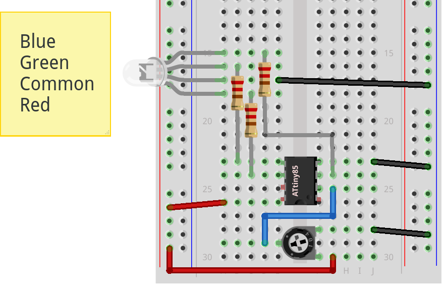
I’ve soldered the final design onto veroboard after prototyping on breadboard:

RGB LED With ATtiny85

I just found that the ATtiny85 actually has 3 PWM pins, not 2 (well you can push it to 4 I believe) so it seemed like the ideal test for my recently received RGB common cathode LED.

I setup the breadboard as shown below (doesn’t look great on Fritzing due to the weird way the LED is drawn sideways) note that the longer pin is the common cathode:

img

I used the arduino-tiny core with the recent round() macro fix for the ATtiny85-20PU at 8MHz, which I programmed using the ArduinoISP sketch. The code is as follows, inspired by Adafruit:

ATtiny85 programming using Mega2560 as ISP

I’ve been burning sketches to an ATtiny85-20PU and burning bootloaders to ATmega328P-PU’s today.

The pinouts below are for the physical pins on the ATtiny85/ATmega328P, and the Arduino pins for the Mega2560:

TINY	MEGA    328P
MISO	6	50      18
MOSI	5	51      17
SCK	7	52      19
RESET	1	53      1
VCC	8	5V      7
GND	4	GND     8

After uploading the ArduinoISP sketch to the Mega2560, add the 10uF capacitor between RESET and GND on the 2560 and upload sketches normally (select “ATtiny85 8MHz internal” as Board) or “Burn Bootloader”.

Arduino Weather Station

I’ve just finished putting together my Arduino-based weather station on breadboard.

I’ve removed the Arduino Mega 2560r3 and put the ATmega328P-PU on the breadboard with some capacitors, a 16MHz crystal, some LED’s, an LM7805 voltage regulator (takes 9V from battery down to 5V) and of course the Nokia 5110 LCD, BMP085 barometric pressure sensor and DHT11 temperature sensor.

I thought the temperature values were a bit off, but both the DHT and BMP give similar readings, so I guess my house thermostat is a couple of degrees out.

Breadboard Arduino/Shrimp Components

Parts lists for my Arduino On A Breadboard, Standalone Arduino and/or a Shrimp projects: