e-Dice
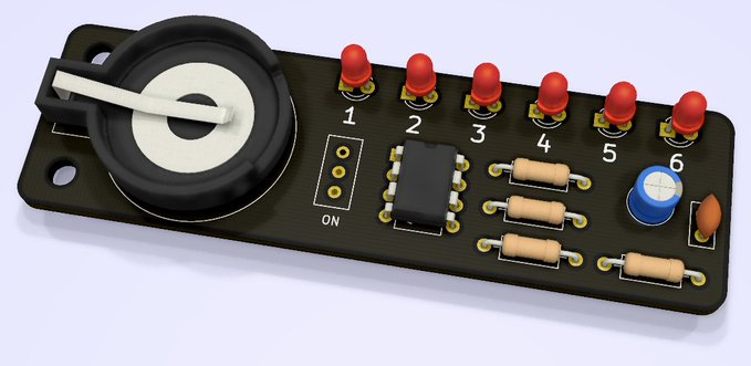
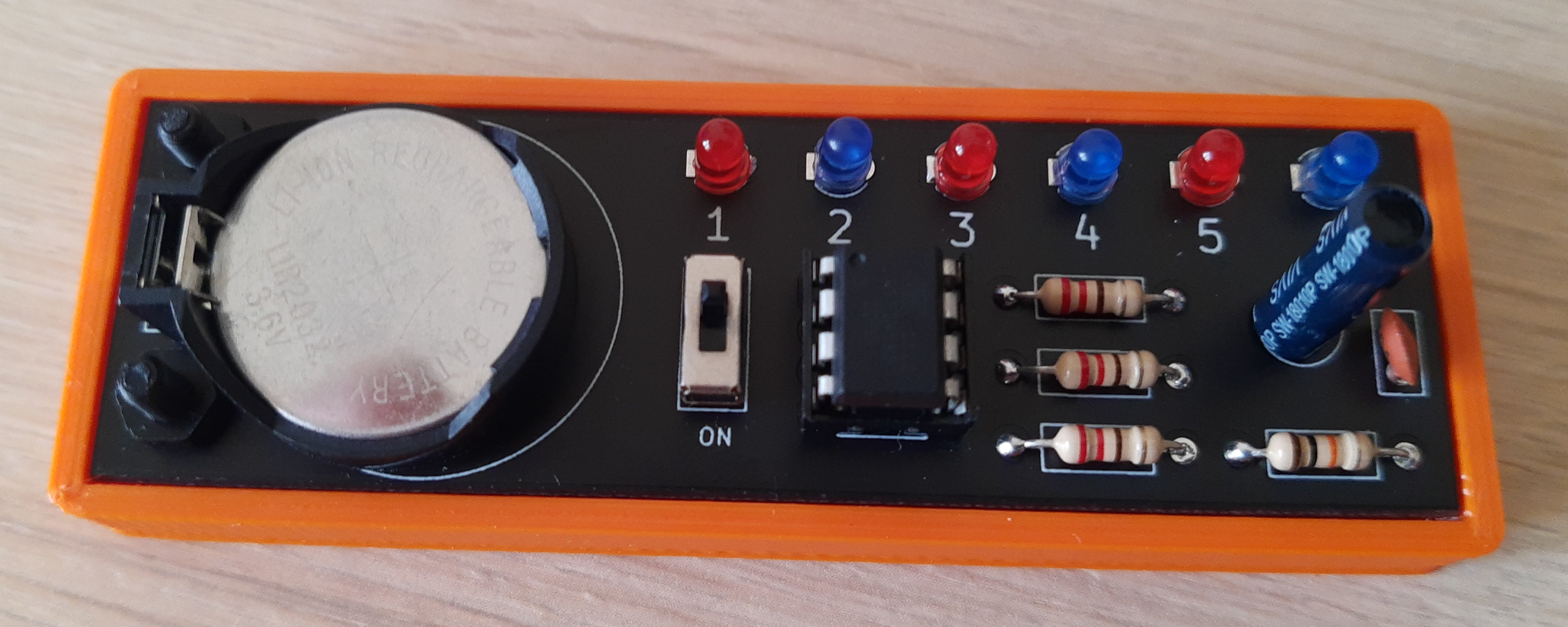
My charlieplexed dice boards have arrived from JLCPCB. It uses an ATTiny85 and vibration sensor and only three output pins to drive 6 LED’s. I’m powering this via a rechargeable LIR2032. I also made a charger for it using my favourite TP4056 modules with Rprog replaced with a 30k resistor to set the charge current to about 35mA, a bit of spare perfboard and a coincell holder (and yet another 3D printed bumper!) It works well as cost under a Pound instead of a tenner or more that the commercial ones cost!
I made a bumper for it, it’s sort of a smaller version of the one used for the decade counters, however I used a sacrificial layer inside the countersunk screw hole, so it came out nicely without supports. The method works well and I will use it for some bigger designs as more of a test.
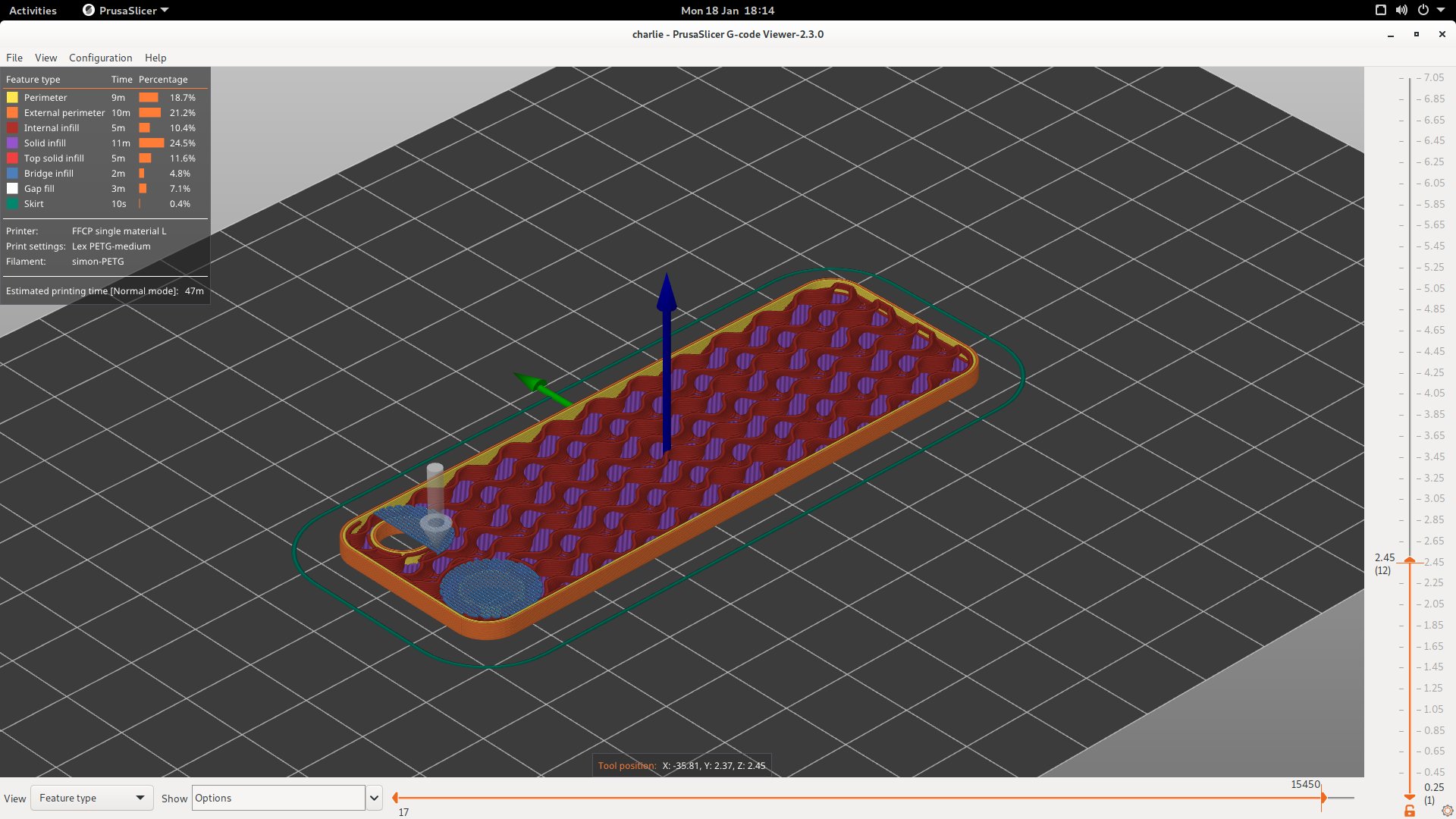
The PCB turned up and I realised the panelization process had removed the rounded corners, so had to modify the bumper case a bit:
And a video of it in action:
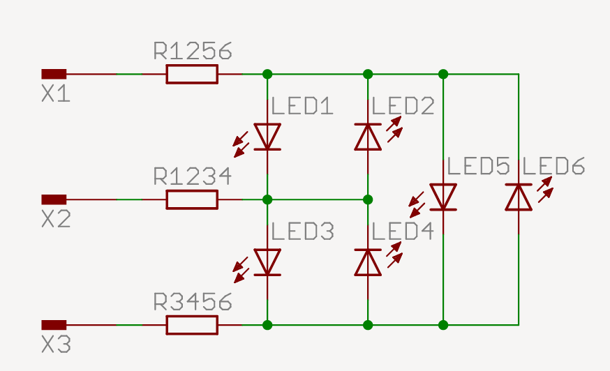
The pinout is as follows, see also the wiring diagram (I inititally made a perfboard version using this):
PB0/D0 = physical 5 = x1 in diagram
PB1/D1 = physical 6 = x2 in diagram
PB2/D2 = physical 7 = x3 in diagram
RST    = physical 1 to vibration/tilt sensor
The code is:
void one()
{
    pinMode(PB0, OUTPUT); digitalWrite(PB0, HIGH);
    pinMode(PB1, OUTPUT); digitalWrite(PB1, LOW);
    pinMode(PB2, INPUT);
}

void two()
{
    pinMode(PB0, OUTPUT); digitalWrite(PB0, LOW);
    pinMode(PB1, OUTPUT); digitalWrite(PB1, HIGH);
    pinMode(PB2, INPUT);
}

void three()
{
    pinMode(PB0, INPUT);
    pinMode(PB1, OUTPUT); digitalWrite(PB1, HIGH);
    pinMode(PB2, OUTPUT); digitalWrite(PB2, LOW);
}

void four()
{
    pinMode(PB0, INPUT);
    pinMode(PB1, OUTPUT); digitalWrite(PB1, LOW);
    pinMode(PB2, OUTPUT); digitalWrite(PB2, HIGH);
}

void five()
{
    pinMode(PB0, OUTPUT); digitalWrite(PB0, HIGH);
    pinMode(PB1, INPUT);
    pinMode(PB2, OUTPUT); digitalWrite(PB2, LOW);
}

void six()
{
    pinMode(PB0, OUTPUT); digitalWrite(PB0, LOW);
    pinMode(PB1, INPUT);
    pinMode(PB2, OUTPUT); digitalWrite(PB2, HIGH);
}

void setup()
{
    // read from unconnected analog pin for entropy
    randomSeed(analogRead(A3));

    // random number 1-6
    long rndnum = random(1, 7);

    // loop through all numbers
    one(); delay(100);
    two(); delay(100);
    three(); delay(100);
    four(); delay(100);
    five(); delay(100);
    six(); delay(100);

    // display final number
    switch (rndnum)
    {
        case 1:
            one();
            break;
        case 2:
            two();
            break;
        case 3:
            three();
            break;
        case 4:
            four();
            break;
        case 5:
            five();
            break;
        case 6:
            six();
            break;
    }
}

void loop()
{
}
And the Makefile for arduino-cli:
# attiny85 8mhz internal oscillator
FQBN = ATTinyCore:avr:attinyx5:LTO=enable,TimerClockSource=default,chip=85,clock=8internal,eesave=aenable,bod=disable,millis=enabled

all:
	arduino-cli compile --output-dir=build --fqbn $(FQBN) $(notdir $(CURDIR)).ino

ispload:
	arduino-cli upload --input-dir=build -b $(FQBN) -P usbasp $(CURDIR)

burn_bootloader:
	arduino-cli burn-bootloader -b $(FQBN) -P usbasp -v $(CURDIR)

clean:
	rm -rf $(CURDIR)/build